Phil designed these Inconel 718 aerospike engines for Land Forces 2021. In addition to the defence samples we already have, we wanted to have some aerospace samples so we can show some design concepts. The purpose of this international expo was to showcase equipment, technology, and services for the armies of Australia and the Indo-Asia-Pacific.
Why did you choose to design an aerospike?
Most aerospace companies use bell-shaped engines, and I wanted to design and print something different. The idea came to me when I was drawing up a model for nozzles for our blasting cabinet and after several internet searches, I found information on the aerospike.
What were the challenges with the design and printing of the aerospike?
Aerospikes tend to get hot on the spike, and I believe that metal 3D printing could solve this issue.
They are usually designed using multiple components and I wanted to try and encompass it in one piece. I wanted to add a few features to help customers with design limitation in build angles and show them how we could use hidden detail. The idea behind this was to print a complete aerospike and a cut-away as per the photos below.
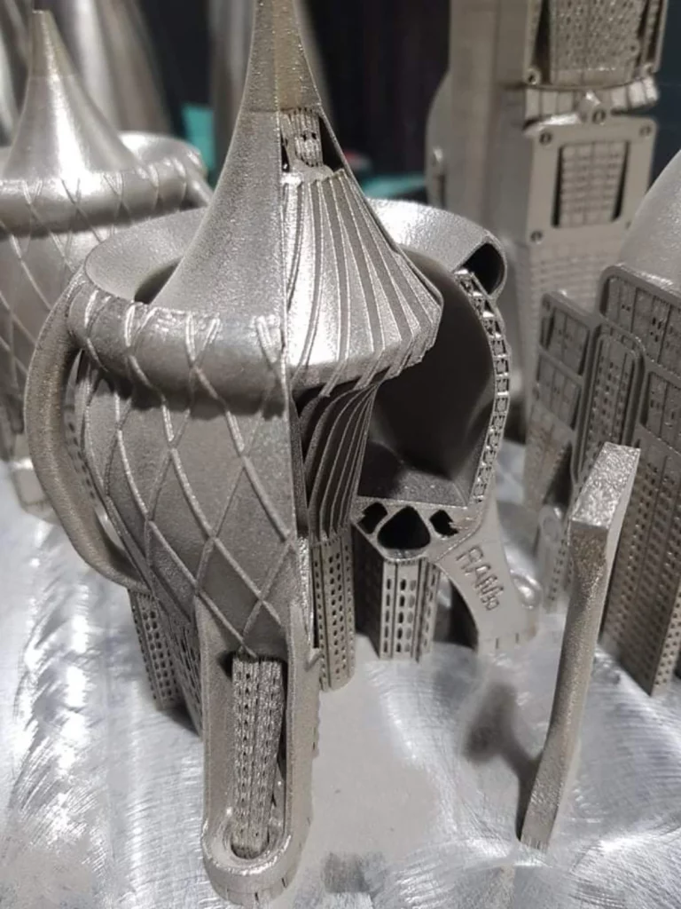
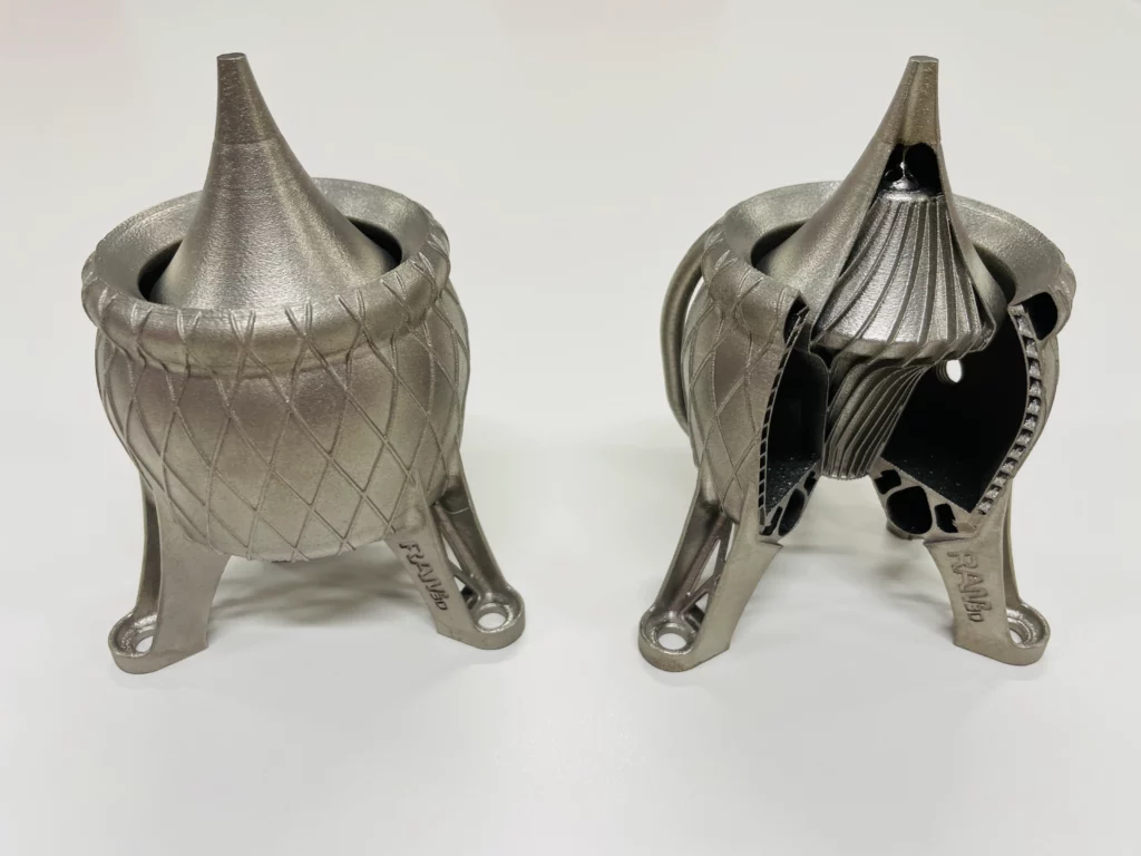
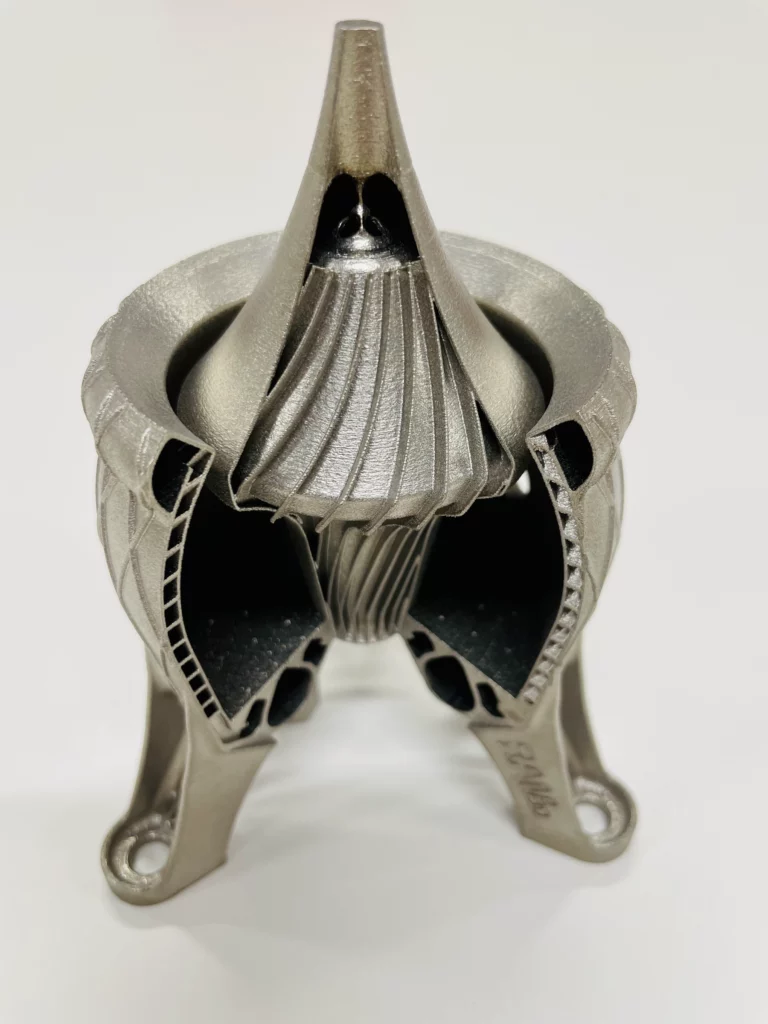
Why did you print it in Inconel?
Inconel 718 is a nickel super alloy used for high temperatures. It has been proven to withstand heat in a harsh environment and it should allow it to work.
Are you going to develop it further?
This project is a work in progress design concept. I want to develop it by adding a gyroid to aid in the cooling of the spike. We will need to conduct some flow analysis to prove it will work and are looking to collaborate with Auckland University to help with this.
It seems complex but it is simple and often 3D printed parts can be simplified more due to the fact they don’t have the same design constraints as other forms of manufacturing.
We shared our recent video on our LinkedIn platform and were asked the following question.
Did the Aerospace work? I’m wondering how the surface finishes of the nozzle affects that?
We explained we hadn’t got to the testing stage, but we believe a small amount of surface roughness is beneficial. The best example is golf balls. By deliberately making the flow at the surface turbulent you can get two different flow steams around the ball.
- Immediate boundary layer which is turbulent and
- Open flow around the ball which will separate later, meaning less drag and better overall flow dynamics.
In short, by disturbing the flow at the surface you can get better flow away from the surface and a lower overall drag/friction outcome. The key of course is having enough without too much!
We also explained we have some experience with other parts used in the same situation and this indicates the surface finish could be working as expected.